The qLib deformer framework
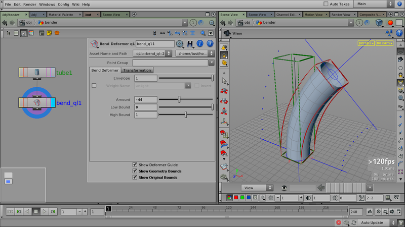
The Bend Deformer qL SOP, applied to a tube. All visual guides are displayed: the deformer guide, and the original (green) and deformed bounding boxes (red). The bounding boxes always fit to the exact bounds of the input geometry.
As soon as you start implementing some deformers you miss from other apps, you realize that (apart from the deformation itself) there’s a certain pattern to them. Long story short, we ended up with a framework concept, which not just deformers benefit from, but some other OPs as well.
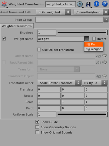
The common UI elements: weighting and transformation (and related functionality, e.g. a weight attribute picker menu).
Features:
- The framework consists of a few common components, a network template (and some design/UI guidelines to follow)
- The common components at the moment are per-point deformer weighting and effect placement.
- Common components are implemented as separate assets (even though we like to keep interdependencies to a minimum)
- Called xform_builder_ql and weight_builder_ql (vex/vop assets)
- The components come with convenience UI functions, e.g.:
- the weight builder has shared weight attribute popup-menu builder code (see right image)
- the xform builder provides a menu for placement presets (fit to geometry, snap to geometry centroid, etc.)
- The components are very easy to apply (in fact, a subnet gallery item is available as template for new deformers).
- They also help simplifying the deformer logic itself (especially transformation-related issues): the deformer has to be implemented in “unit space”, the xform builder does the rest.
- Visual guides are implemented in a similar fashon —
- There are templates that build the original and deformed bounding boxes for the input geometry for display guides (see first image). These provide important visual feedback for the user.
- Since the resulting operators have a lot of parameters and behaviour in common, they provide the user with a familiar interface.
The common parameters are the following:
- Weighting
- Envelope: an overall weight percentage value (0: no effect, 1: the weight map is in full effect)
- Weight Name: name of a per-point float attribute (if disabled, only Envelope applies)
- Invert: inverts weight map attribute values
- Transformations
- Use Object Transform: use an OBJ level node as transformation (instead of the TRS parameters, below)
- Object Name: the OBJ level node name
- Rest/Parent Obj: if enabled, the relative transformation between this object and the transform object will be used as transform
- (TODO: explain xform space conversion)
- Regular xform parameters: these apply if Use Object Transform is off
The following are a few screenshots of the bend deformer’s internals — most other deformers are built the same way.
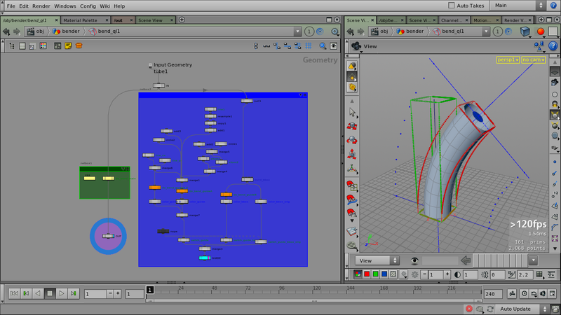
The green section performs the actual deformation, the blue section generates display guides. (Although the blue might seem overly dominant, in reality it isn’t — deformer complexity is one layer below. See next images.)
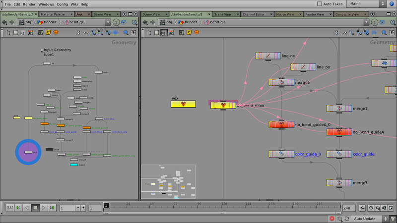
Since the deformation function has to be called multiple times (once for the actual geometry, and multiple times for guide displays), it is stored in a VEX context that shows up as a new VEX node type as a result, which can be reused multiple times. The yellow OPs are the VEX container and the main instance (geometry deformation). The orange OPs are referenced copies of the main instance (doing guide displays).
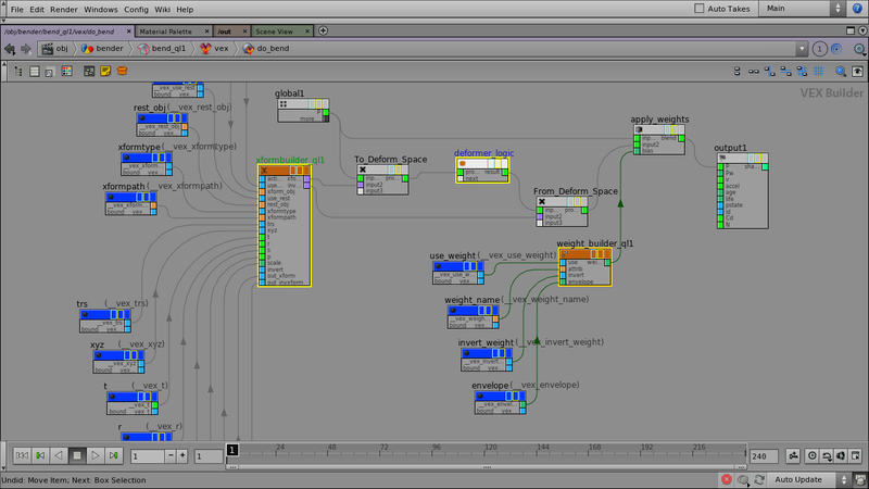
The main VEX-level is almost always the same: an xform_builder_ql generates transformations to/from “placement space”; a subnet called deformer_logic (containing the deformer itself); and a weight_builder_ql, applying any weight maps/envelopes.
(There can be minor differences with certain deformer types, for instance ones where points are displaced along a direction vector.)
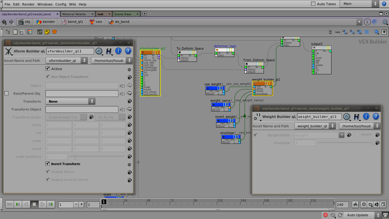
The parameters of xform_builder_ql and weight_builder_ql are (not surprisingly) almost exactly the same as in the main interface.
Houdini OP colors
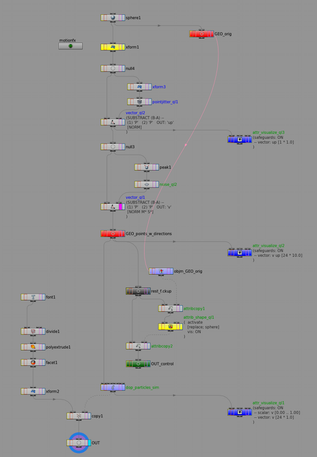
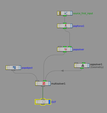
This first image is an example of how I use OP colors and layout throughout Houdini.
I color as few nodes as possible, and use a “sparse” layout style. This leaves enough space for any new OPs, and gives a clear picture if you zoom out to a birds-eye distance.
The visualizer (display-only) nodes are separated from the rest. They often mark the end of a network section (and the visualizations usually show the results of each section).
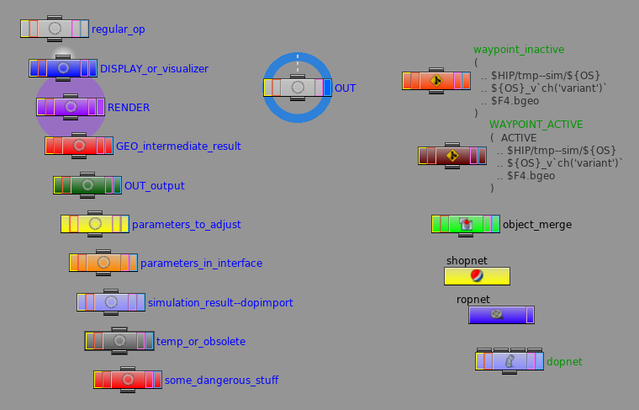
I worked out the following coloring/naming scheme:
- I use the default (gray) for almost all nodes (obviously).
- The display and render colors come from the corresponding flag colors.
- I use the mandatory fixed node names OUT, DISPLAY and RENDER (this allows for a script to set up all the corresponding flags for all networks in the scene).
- I build my networks in sections and end each one with a node I call a “waypoint” (this is either a regular Null OP — or a Waypoint qL SOP if I want to write the intermediate results to a file.)
Left coloumn, top to bottom:
- Display: it’s either a node to hold the display flag (with a mandatory name DISPLAY), or a node to show some visualization (usually an Attrib Visualizer qL SOP)
- Render: node for holding the render flag (with a mandatory name of RENDER)
- Out: it’s the output. Its name is fixed (OUT) and it always exists, even if I have display/render. In that case it’s the geometry that is considered final — except any render-specific setups –, that can be passed along to a next network.
- Intermediate result (or “waypoint”): a null node with GEO prefix
- Named output: a null with an OUT prefix — contents of this node will be used elsewhere (some other network).
- Parameters to adjust: the node has parameter(s) that are considered adjustable params for the effect (and would be published for a finalized asset).
- Parameters in interface: parameter(s) on this node are already published as OTL parameters.
- Simulation result: this node fetches the results of another processing network (it’s usually simulations, and this is a dopimport node.)
- Temp (various shades of darker gray): this node is either temporary, or becoming obsolete — anyway, soon it’ll be deleted.
- “Dangerous”: this node represents something dodgy:
- Some quick-and-dirty hackety-hack
- An operation that depends on a certain topology of the input geo (component indices, etc.) in the middle of a network that’s supposed to be topology-independent (e.g. blasting some stuff away after a simulation)
- …
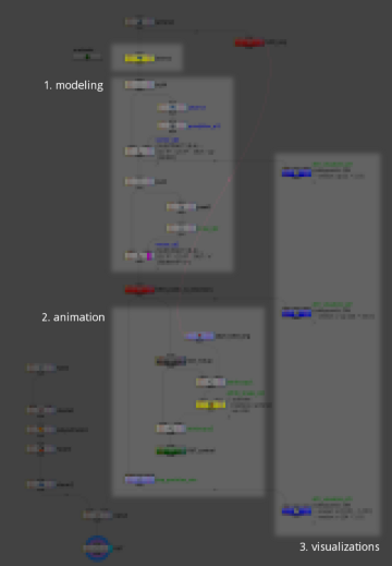
A bird’s-eye view of the same network, with each section highlighted:
…
—
ps.: By the way, the results of the above network can be seen here: https://vimeo.com/88498440 — for completeness’ sake, the dopnet looks like this:
(But the big secret is in the sopsolver anyhow! ;))
dpkg cheat sheet
git: delete remote branch
git push origin :<branch to delete>
Houdini special: variable modifiers
This is cool: Variable modifiers
(For instance, $HIPNAME:r returns the scene file name without the extension.)
houdini quickie: divide ‘particle fluid surface’ output geometry
The Particle Fluid Surface SOP can create some very messed-up polygons sometimes — it’s well worth triangulating it using (say) a Divide SOP.
(Within Houdini it might not casue problems, but other apps — like Maya — aren’t that tolerant.)
git: link local branch to remote branch
git branch --set-upstream master remotes/origin/master
(From here.)
home computer OS update
Did a new install of Ubuntu 10.04 (because of LTS — I don’t want to touch the stuff for several years).
I have nvidia driver version 275.09.07 installed, and I’m having problems constantly. I’ll have to downgrade to an older version (I wish I knew how to find out which one is the most stable).
git: fetch branch from remote repo
git fetch <remote repo> <remote branch>:<local branch to create>
